Anchor-Body Mechanical Properties
The published ultimate and yield strengths relate to the mechanical properties of the anchor body. They are not an installed holding-capacity rating for the complete anchoring system.
The HP25 is the smallest anchor in the range. It is manufactured from glass-reinforced nylon and can be supplied with wire-rope or threaded-bar connection arrangements.
The HP35 is a compact galvanised ductile-iron anchor with a larger bearing area and higher anchor-body strength than the HP25.
The H range consists of the H50, H80 and H110.
The three models share common overall height and length dimensions but provide progressively larger widths and soil-bearing areas. This allows the bearing area to be changed while remaining within the same general anchor family.
The H range can be configured with wire rope, chain or threaded-bar connections, depending on the application.
The HG100, HG180 and HG320 form the heavy-duty HULK Earth Anchor range.
All three HG models have the same published anchor-body mechanical properties but provide substantially different soil-bearing surface areas. Assemblies can be developed using project-specific wire rope, chain, rod and connection arrangements.
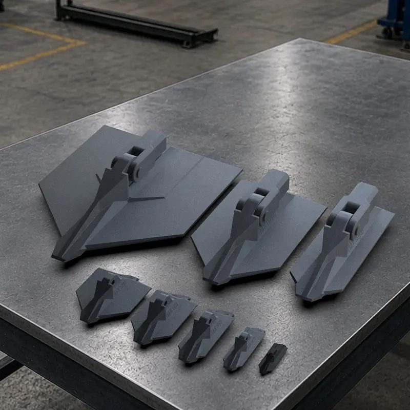
Hulk Earth Anchor range, from the largest HG320 (Top Left), to the smallest HP25 (Bottom Right)
| Anchor | Dimensions | Weight | Material | Mechanical Properties | Soil Bearing Surface Area | Typical Installation Depth |
|---|---|---|---|---|---|---|
| HP25 | 25 X 25 X 85mm | 0.017kg | Glass-reinfored nylon | Tensile Strength 5kN | 18.42cm² | 0.6-1.2m |
| HP35 | 35 × 47 × 125mm | 0.285kg | Ductile iron TDG galvanised |
Ultimate: 30kN Yield: 19kN |
38.75cm² | 0.9–9m |
| H50 | 50 × 63 × 160mm | 0.75kg | Ductile iron TDG galvanised |
Ultimate: 75kN Yield: 45kN |
69.32cm² | 1–9m |
| H80 | 80 × 63 × 160mm | 0.835kg | Ductile iron TDG galvanised |
Ultimate: 75kN Yield: 45kN |
99.8 cm² | 1–9m |
| H110 | 110 × 63 × 160mm | 0.99kg | Ductile iron TDG galvanised |
Ultimate: 75kN Yield: 45kN |
126.6cm² | 1–9m |
| HG100 | 100 × 105 × 341mm | 5.25kg | Ductile iron TDG galvanised |
Ultimate:280kN Yield: 175kN |
298.96cm² | 2.1–9m |
| HG180 | 180 × 105 × 341mm | 6.4 kg | Ductile iron TDG galvanised |
Ultimate: 280kN Yield: 175kN |
487.76cm² | 2.1–9m |
| HG320 | 320 × 111 × 444mm | 11.3kg | Ductile iron TDG galvanised |
Ultimate: 280kN Yield: 175kN |
1034.54cm² | 2.1–9m |
The published ultimate and yield strengths relate to the mechanical properties of the anchor body. They are not an installed holding-capacity rating for the complete anchoring system.
The soil-bearing area describes the reaction surface presented by the anchor head. A larger bearing area does not, by itself, establish the installed capacity.
The listed depth range is indicative. The required installation depth for a particular project depends on ground conditions, anchor response, required loads, installation equipment and project-specific requirements.
Installed holding capacity is influenced by:
The appropriate HULK Earth Anchor should be considered as part of a complete system rather than selected from one specification alone.
Relevant information includes:
The working, design, proof-test and lock-off requirements should be identified where available.
Provide geotechnical information, bore logs, soil descriptions or previous test results where these are available.
The required depth and orientation may influence the anchor model, tendon, installation equipment and testing arrangement.
The anchor must be connected to the supported asset or structure through an appropriate tendon, termination and connection detail.
The intended service period and environmental conditions may affect material, galvanising and corrosion-protection requirements.
Restricted access, overhead limitations, underground services, slope conditions and available plant can influence the installation method.
Project specifications may require a particular proof-test load, acceptance criterion or installation record.
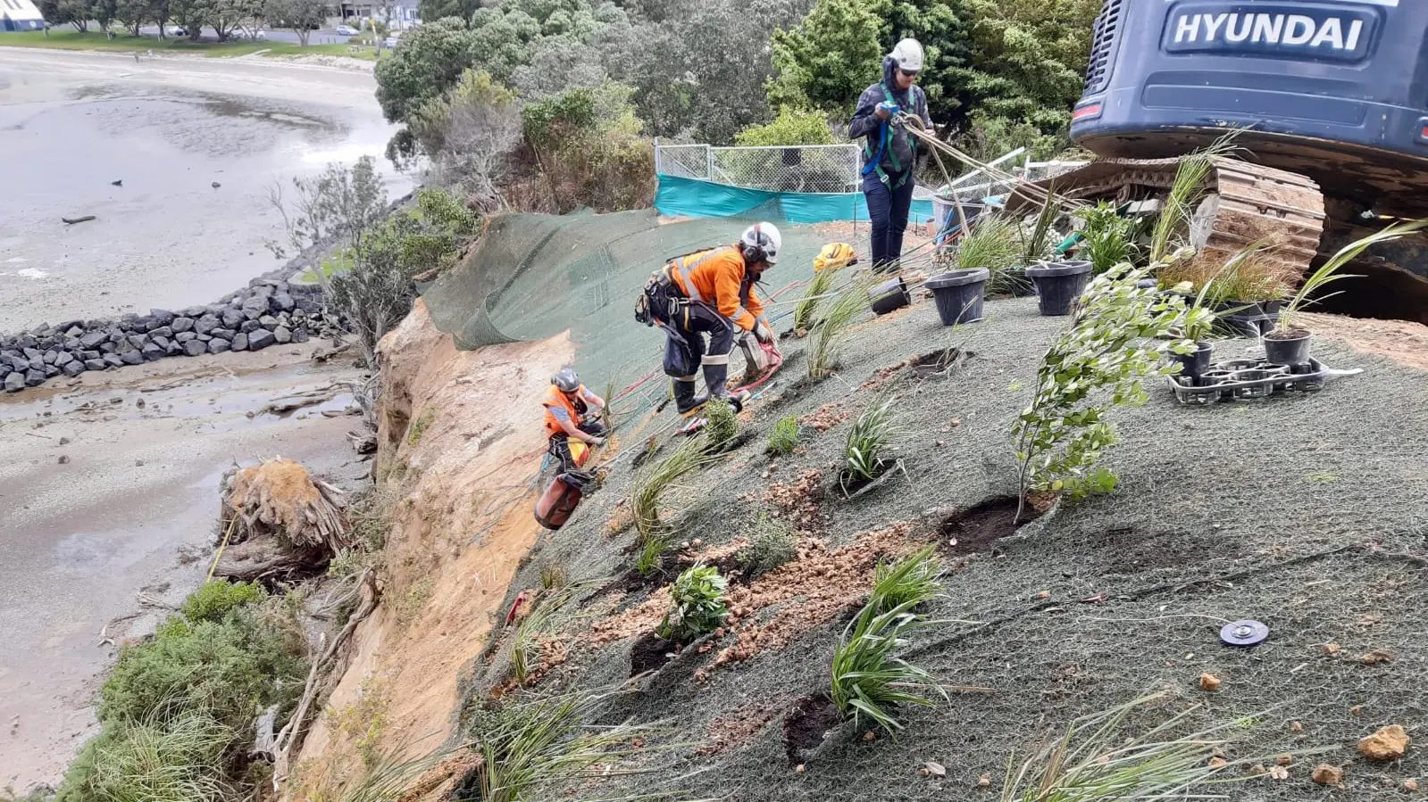
Hulk TRK (Turf Reinforcement Kit) anchors installed through TRM to stabilize soil on slopes, and prevent erosion from wind, rain, and water run-off
Depending on the anchor family and application, HULK Earth Anchors may be configured with:
Standard options and project-specific assemblies are available. Detailed assembly selection should be confirmed with AR+R rather than inferred from anchor-head specifications alone.
Note
The mechanical properties shown above apply to the anchor body and do not represent the installed holding capacity of the complete earth anchor system. Installed performance is dependent on the anchor, tendon, ground conditions, installation depth and quality of installation. Proof testing or project-specific engineering assessment may be required.
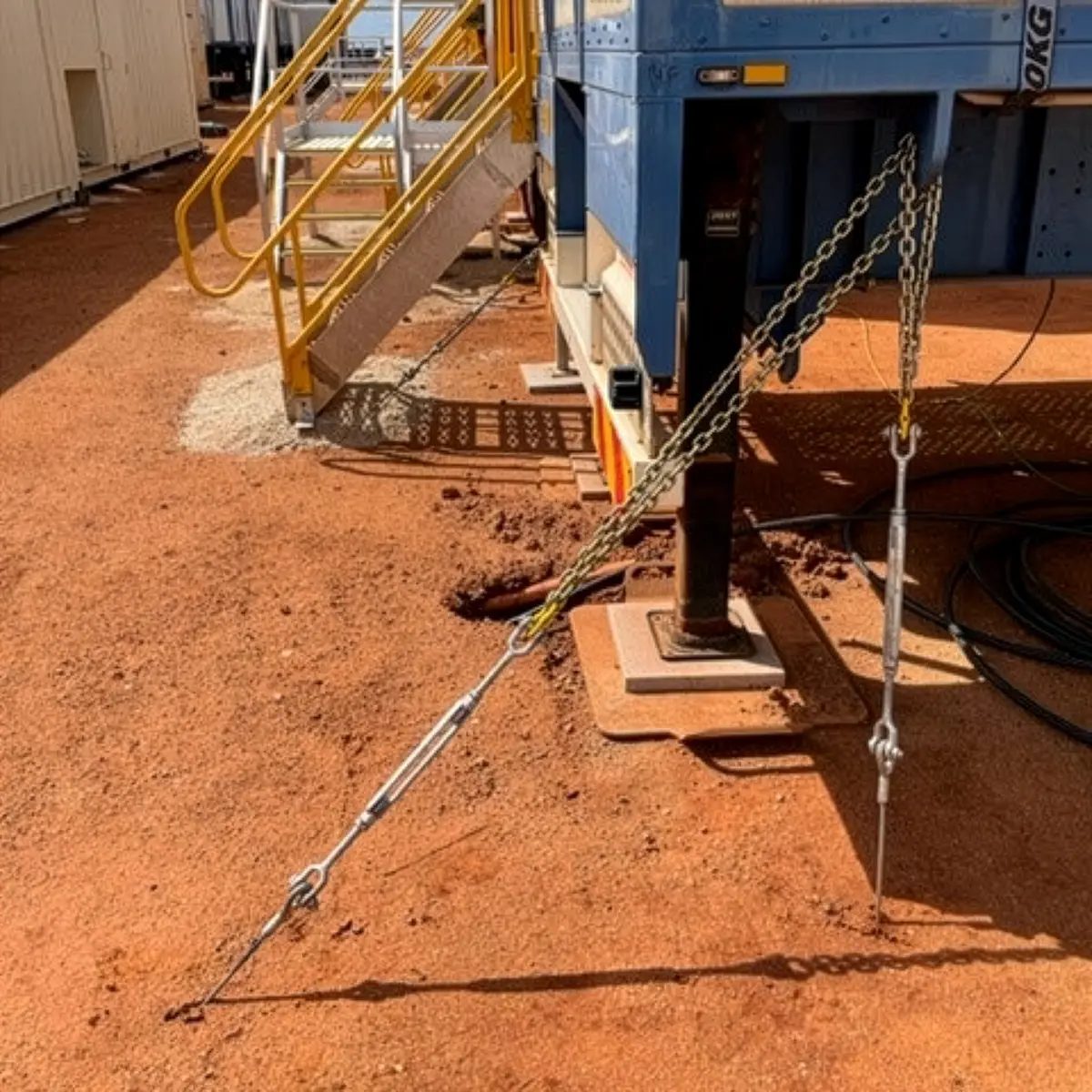
Portable structure tied down to Hulk Earth Anchors using chain and turnbuckles.
Submit your application information for an initial review by AR+R.
Helpful information includes:
Fields marked * are required.
Please check the highlighted fields and try again.